
Currently Empty: ₹0.00

TRAINING CONDUCTION DETAILS
With Industry Expert
Training Mode: Recorded (Lifetime Access)
Language: Hindi
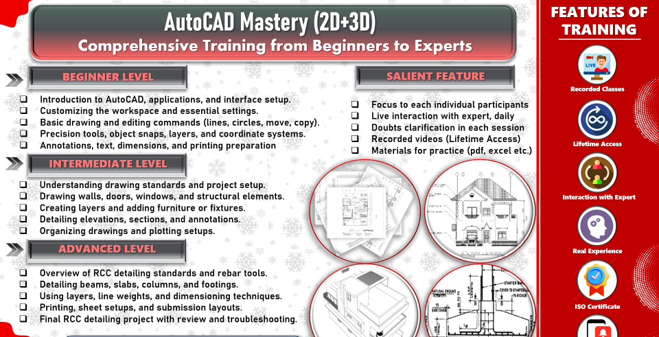
ABOUT THIS TRAINING
Master AutoCAD with our hands-on training program! Learn essential 2D and 3D modeling skills, drafting, and documentation to create precise, professional designs. Perfect for architects, engineers, and designers looking to unlock the full potential of AutoCAD.
COURSE MODULES
The Foundation (Environment & Standards)
Before drawing a single line, we must ensure the “digital paper” is set up correctly. A structural drawing must be mathematically precise and consistent across hundreds of sheets.
Unit Coordination: Setting up decimal vs. architectural units using UNITS and the critical -DWGUNITS command for internal scaling.
Layer Management: Creating a standard structural template.
Layers: S-GRID, S-CONC-OUTLINE, S-REBAR, S-TEXT, S-DIM.
The Structural Grid: Using XLINE (Construction Lines) and OFFSET to establish the primary building axes.
Object Snaps (OSNAP): Mastering “Node,” “Intersection,” and “Perpendicular” to ensure rebar always hits the center of a column.
Drafting Structural Elements (The Components)
We move from lines to recognized structural components. This module teaches “smart” drafting to avoid repetitive manual work.
Dynamic Blocks: Creating a “Column Block” that can be resized from 300\text{mm} \times 300\text{mm} to 600\text{mm} \times 600\text{mm} without exploding the geometry.
Polylines & Regions: Using PLINE for slabs and BOUNDARY to create closed shapes for area calculations.
Hatch Patterns: Standardizing symbols for concrete (AR-CONC), earth, and masonry to ensure clarity in sections.
The Array Command: Efficiently spacing floor joists or rafters across a bay using ARRAYPATH.
Module 3: Detailing & Reinforcement (The "Zoom-In")
This is the core of structural drafting—showing exactly how the steel sits inside the concrete or how the steel plates bolt together.
Sectioning: Using CLIP and XREF to create detailed sections from a general floor plan.
Reinforcement Callouts: Drafting “L-bars,” “Stirrups,” and “Main bars” using specific line weights.
Leader Lines: Mastering MULTILEADER (MLEADER) to label bar sizes (e.g., 4\text{#}16 @ 150 c/c).
Standard Details: Managing a library of “Typical Details” (e.g., beam-column junctions) to be reused across projects.
Module 4: Annotation & Scaling (The Professional Polish)
A common mistake is drawing text that is too small to read on-site. We solve this with Annotative Scaling.
Annotative Styles: Creating text and dimensions that automatically resize based on the viewport scale (1:20 for details vs. 1:100 for plans).
Dimensioning: Using DIMLINEAR and DIMCONTINUE for grid-to-grid measurements.
Tables & Schedules: Using the TABLE command to create BBS (Bar Bending Schedules) directly in CAD.
Data Extraction: Automatically counting the number of columns or bolts in a drawing and exporting to Excel.
Module 5: Sheet Composition & Plotting (The Final Deliverable)
The “Model Space” is for drawing; the “Layout Space” (Paper Space) is for presenting.
Viewports: Creating multiple windows on one sheet to show a plan at 1:100 and a detail at 1:10.
CTB Files (Plot Styles): Assigning colors to line weights (e.g., Red = 0.1\text{mm}, Yellow = 0.5\text{mm}) so the printed PDF looks crisp and professional.
Title Blocks: Creating attributes for project names, dates, and revision numbers.
Batch Plotting: Using PUBLISH to turn a 50-page structural set into a single PDF in one click.