
Currently Empty: ₹0.00

Training Program Details
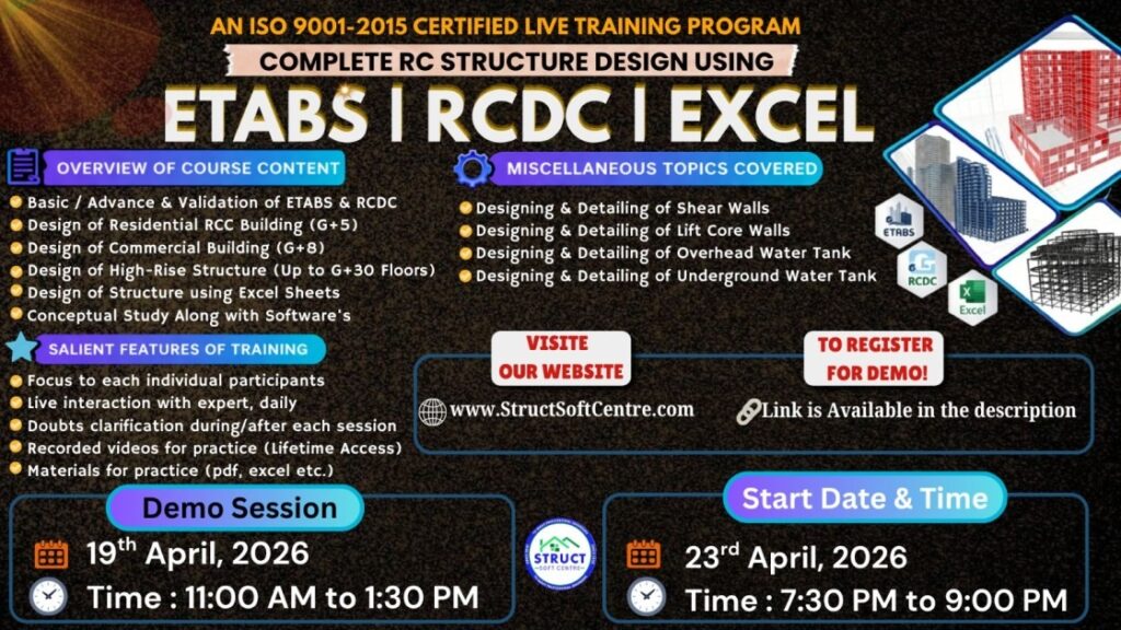
ETABS
With Industry Expert
Course Duration: 2 Months
Training Mode: Live + Recorded (Lifetime Access)
Live Session Timing: 7:30 PM to 9:00 PM
Time Table: 6 Days in a Week
Language: English
ABOUT THIS TRAINING
Structural engineering is one of the most demanding specializations of civil engineering. Now a days dealing of real-life challenging projects by conventional approach is too difficult. Industry demands both conceptual understanding of structure and deep knowledge about the trending softwares.
COURSE MODULES
Module 1: Geometry & Property Definition
This is the “Pre-Processing” phase. If your units or material strengths are wrong here, the entire design is invalid.
Material Non-linearity: For concrete, we define the characteristic strength (f_{ck}); for steel, the yield strength (f_y).
Section Modifiers: This is critical. We apply “Cracked Section Modifiers” (e.g., 0.35I_g for beams, 0.70I_g for columns per ACI 318) to account for concrete cracking under service loads.
Object Modeling: * Beams/Columns: Modeled as line elements.
Walls/Slabs: Modeled as area elements (Shell-Thin).
Module 2: Load Patterns & Applied Forces
We distinguish between forces that act vertically (Gravity) and those that act horizontally (Lateral).
Dead Load (DL): Automatically calculated by ETABS based on the geometry and material density.
Superimposed Dead (SIDL): Includes floor finishes, MEP conduits, and fixed partitions.
Live Load (LL): Occupancy loads based on code (e.g., 2.0\text{ kN/m}^2 for residential).
Seismic Load (EQ): Defined using the Response Spectrum or Equivalent Static method. You must input the Seismic Zone Factor, Importance Factor (I), and Response Modification Factor (R).
Module 3: Diaphragms & Meshing Logic
This module ensures the software “connects the dots” correctly between floors and walls.
Rigid Diaphragms: Assigned to floors to ensure the entire level moves as a single plane. This is essential for calculating the Center of Mass (CM) and Center of Rigidity (CR).
Manual vs. Auto-Mesh: While ETABS has an “Auto-Mesh” for slabs, a structural designer often uses a manual 1\text{m} \times 1\text{m} mesh for complex shapes to ensure nodes align perfectly between slabs and beams.
Support Conditions: * Fixed: Resists moment (common for pile caps/rafts).
Pinned: No moment resistance (common for steel base plates).
Module 4: Analysis & Behavior Checks
Once you hit “Run Analysis,” you aren’t looking for rebar yet—you are looking for structural integrity.
Modal Mass Participation: You must achieve >90\% participation in X and Y directions within the first few modes to ensure the dynamic analysis is valid.
P-Delta Analysis: For tall buildings, we enable P-Delta to account for the secondary effects of gravity loads acting on a displaced structure.
Story Drift: We check if \text{Drift} < \text{Allowable Limit} (usually 0.004 \times \text{Story Height}). If it fails, the building is too flexible and needs stiffer columns or shear walls.
Module 5: Design & Output
This is the “Post-Processing” phase where we extract actionable data for the construction site.
Concrete Frame Design: ETABS provides the longitudinal rebar area (A_{st}) in \text{mm}^2 or \text{in}^2. We check for “O/S” (Overstressed) members.
Shear Wall Design (Piers): We group wall segments into “Piers” to get a single P-M resultant, allowing us to design the wall cage.
Punching Shear: Checking if columns will “punch” through flat slabs.
Detailing: Exporting the results to CSI Detail or REVIT to produce the actual reinforcement drawings.